Artmouth Cove
My main exhibition layout, “ELMGATE STATION”, has reached a state of completeness where any further changes will be evolutionary, rather than revolutionary. I have had several new projects on the go, so really do not need another. However, when I saw an unfinished layout on Ebay in the autumn of 2012, and noticed the location was within 30 miles of home, I put in a “silly” bid. The only other bidder was even sillier, so I won the layout for a snip!
Having picked it up, I had to decide what on earth I would make of it. I started by assessing what the builder had completed, and what was intended. The track plan (which I have drawn and annotated with my own descriptions) is this [Click on pictures for larger version – close to return]:
Track Plan

Line diagram of Track
The points, except for “B” were already fitted with PECO motors. Wiring was in place from the Main Line, Loco Release, and both siding isolated sections. However, the seller pointed out that the isolation gaps did not have insulated fishplates. All the points wiring was brought to a terminal block on the rear of the layout, with the section wiring loose in the same position.
LATEST NEWS: I have created a separate page for updates. Continue to read this page for the history of this layout, or go straight to the Progress Page.
I started by fitting the insulated fishplates. To do this, I had to remove some track pins, and in the process managed to rip the rails from the sleepers of the Loading Dock siding. The missing point motor would need some thought, as one fixing would be in thin air (the motors had been screwed beneath the board, rather than cutting a large hole and attaching to the points). These photos show the condition of the layout when I started again in mid March 2013.

Overall view

Right hand end

Left hand end
First stage of reconstruction
I tackled the missing point motor first. By use of a Peco mounting plate, I made a brass plate, which I could fasten one end of the mount to, and then screwed the brass plate under the layout, with 3 screws, one either side of the mount, and the last through the second mount hole.
 To allow for the extra thickness of the plates, I used the long shaft point motor. To augment the frog switching, I added Peco switches to all four motors.
I decided that the direction of viewing the layout would be as I have taken the photos, and the drawing. I wanted to control from the front, so re-routed the wiring to the front right hand corner. Some wires were long enough to reach the new position; for those that were too short, I relocated the terminal block inside the underside of the layout. New wiring was then taken to the control point.
Initially, a small panel was made, and attached at the desired position. This contained two switches for the Main Line and Loco Release, plus rivets in the diagram for point changing:

The 5-pin DIN socket is wired as standard for my hand-held controller. The large yellow wire is the points prod. You will note that I removed part of the front fascia, to fit the panel. The problem with the original fascia is that, being plastic, the newspaper scenery has not remained glued to it. I therefore planned to replace at least the front and right side with mdf.
At this point, I posted the layout on the Narrow Gauge Railway Modelling forum, and asked for reactions, and ideas for going forward. The response was encouraging, and recommendations for fishing boats, etc. were received. I was concerned about the two water channels, but was reassured that this would not be impossible for a small harbour. Suggestions for locating the line in Devon/Cormwall or East Yorkshire (Whitby) were received. In the end, I decided….
Location
Although I did not originally mention it, I was thinking along the lines of “West Country”. However, I fancied bringing it a little east, to the south east Devon Jurassic coast at Lyme Bay. There are plenty of examples of standard gauge lines from the South Western mainline to Exeter (Lyme Regis, Axmouth/Seaton, Sidmouth, Otterton, and Exmouth). So why not a narrow gauge line down an otherwise inaccessible valley? The interchange point does not need to be with the west of England line itself, but could be one of the aforementioned branches.
As well as replacing the line to the Goods loading dock, I decided to lower the line alongside the quay by about 10mm, to ease the access from the quayside, and to introduce some changes in level. I was encouraged to include a tall derrick on the left of the quay itself to cater for handling cargo from the railway to a ship moored at the quay.
Progress on the layout was stopped by the need to prepare Elmgate for an exhibition. However, by chance, at my local 009 modelling group, one of my colleagues brought some buildings rescued from his former layout, which he had dismantled due to impending house move. I picked up a few, which I knew would suit the Harbour layout. I have placed them in position for some photos:
Layout with test positioning of buildings

Front of Layout

Rear of Layout

Station Building and Loading dock

Water Tower

Chapel and Signalbox
Since I felt the station building was rather small, and I had some spare parts from an equivalent Ratio station shelter, I decided to convert the two into one.
Assembly of the extended station building

Original station building and parts for extension
Part 2 was used to take the place of the original left hand end (4). Since this part is non-symetrical, and was now to face the opposite direction to the intended use, it was necessary to remove the right (rear) vertical. The left hand (front) vertical was carved back to the level of the horizontal planks, and the lapping filed back. A new vertical was then added alongside at the front.
Part 3 became the new front of the left hand room. The gable section was removed, to make the part the same height as its equivalent. In a similar way, the rear face (plain) was cut from part 1. A ticket window was cut and filed into part 4, with the serving hatch formed into a piece of transparent plastic, and fixed behind the aperture. A canopy was added over the window, using parts from the gables previously cut off one of the other parts, and excess roof material.

Front of new station building

Left of new station building with Ticket window
The parts were assembled onto a new floor of black 1.5mm plastic card. The extension roof was cut from the spare roof parts.
The original chimney for the right hand end was missing (only the brick section on the rear wall was there). I added the “H” section chimney above the roof. The complete chimney from my second kit was assembled as designed, with some modification to the left hand rear wall (part 1) to accomodate the brick section. The chimneypot itself was a whitemetal casting from Langley models.

Rear of new station building
The whole was repainted using acrylic paints (a first for me) in a green to match the original.
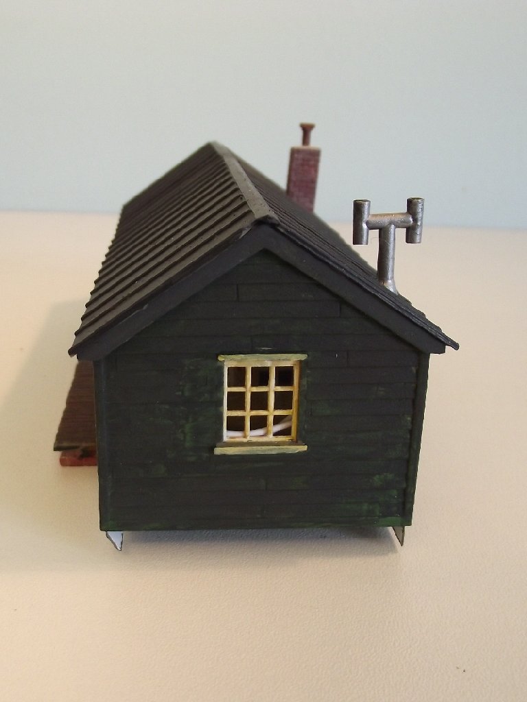
Right of new station building (original end)
In the end, I did not use the second planked floor, nor the window at the front of the first picture.
What’s in a name?
Around the same time, I decided on a name for the Harbour – “Artmouth Cove”, and the Railway is “Art Valley Light Railway”. There are several reasons behind this:
I wanted a 3-letter name for the river, in common with many Devon rivers. Sidmouth has the river Sid, so I decided on Art.
I have a set of Southern “River Class” loco nameplates, including RIVER DART – just cut the “D” out, and you have ART (yes I have done it).
The station building that I purchased already had “A V L R” on the notice board.
By late July 2013, Work on Artmouth Cove had progressed to an operable state. I constructed a small (note – small does not mean easy or quick!) Fiddle Yard, as a sector table format. The Quay line now dropped toward the quayside, although a derrick will still be required to lift the produce from the landing area. I replaced the Goods track that I ruined. Also the main line across the bridge, to repair the end damage. The front and right hand fascias are new.
I also renewed the Control Panel, as I realised that this was too small. In the course of fitting the necessary frog polarity switches, I concluded, as many others have, that it is virtually impossible to get the PECO switches to make reliable contact in both positions. Since I had a store of suitable 12V relays, I decided to arrange the point motor switches so that they make positive contact in one direction (the “reversed” position of the points) and feed a relay coil for each point. Since the relays have two sets of changeover contacts, I used one to switch the frog polarity. The second set supplies green LEDs in the Panel, thus showing the setting of the points.

New Control Panel with LED indication of Points

New Fiddle Yard

Artmouth Cove from Fiddle Yard end

Station area, with initial placing of buildings etc.
Quay line, dropping to end.

Bridges at Fiddle Yard end
Instead of cross sleepers on the bridge, I have placed longitudinal beams of copperclad. I have yet to fit the angles to hold the track to gauge.

Detail of bridge

Fiddle Yard exit
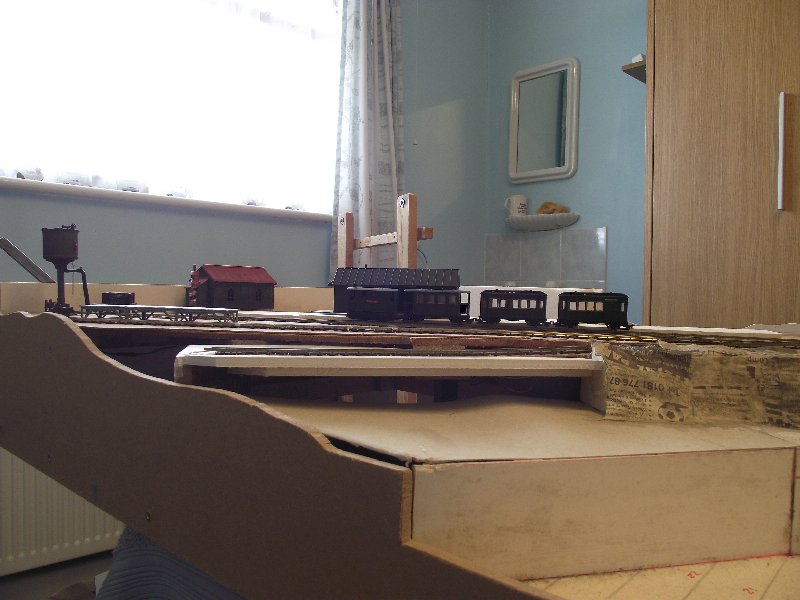
By the end of August, I had fitted the left and rear fascias. I also added another building, and started the scenic work, with the road rising toward the rear left:

Station Area
The station area, with loco “RIVER ART” and 3-coach train. In the left background is the first of some card buildings. These were supplied as kits by Kelloggs in the 1980’s,to the best of my recollection, and I have had them ever since, but never assembled them. For ARTMOUTH, I assembled the Ferry Inn kit, using thick card as stiffener. As may be seen in later pictures, the road is on a slope, so I will need to raise the near end, and inset the far end into the ground. The tin tabernacle has now found its permanent home here next to the loco facilities.

Pub and village from left hand side
Looking down on the village area. The section of scenery immediately behind the station building will become the narrow track into the railway yard. The main road from the river bridge climbs to the left as a continuation of the slope from the bridge. The pieces of paper to the left (rear) of the road are templates for the remaining buldings, including a petrol station/car servicing area, and the usual butchers/bakers/grocers/sweet shop and post office. The triangle immediately in front of the Inn will be a “village green”.

Quay line
The quayside line. One of my respondants mentioned that Fish Vans would be required. With some suitable lettering, these Egger/Jouef vans will become the AVLR’s equivalent of the Flying Kipper! (Thomas the Tank fans will know what I mean). I have inserted a long screw at the end of the line to prevent the inevitable, until such time that I complete the area with a solid concrete buffer stop.

From left rear
A view from the rear, probably showing more of the clutter in my room than of the layout! You can just make out that the buffers (PECO 009) have been painted red. The slabs on the platform show up better in this shot.

Tram coaches
The second passenger set is formed of these Egger/Jouef tram coaches. The bogie one is a rebuild of several originals, and requires replacement steps. The 4-wheel one is a cut down version on original Egger coach chassis. This shows the Inn rather better, too.
I have added uncoupling magnets. Two are permanent, one of which is between the loco and front coach; the second is on the quay line, just in the right place to uncouple three short wagons. The two electromagnets are – one in the platform line, just to the rear of the coaches in the photo above, to enable wagons to be detached from a “mixed” train. The second is at the throat of the loop. Couplings are a mix of my traditional DG, with remote uncoupling tongue, and the others being the standard Egger type, with a iron wire tail to actuate the loop raising. To make these suitable for remote uncoupling, I have added a (non-magnetic) wire as seen to the right of the bogie coach. The procedure is to stop over the magnet, thus raising the coupling loop, back away until the loop rises above the level of the wire, and then proceed forward, with the loop now above the wire. The stock can then be left where needed. This method was developed by Paul Windle and the Hull MRC, on their “Roth Valley” layouts, including Crumley and Little Wickhill, and I acknowledge their design.
